Flow Control Unit

Smart Temperature-Dependent Valve Management with Turnkey Integration

Our client required a solution to control a valve based on real-time temperature readings, with provisions for future expansion to two additional valves. The system needed to include manual override functionality and be controllable via a Raspberry Pi Zero. The goal was a reliable, fully integrated solution combining hardware, software, and system-level management, delivered as a ready-to-install unit.

We delivered a complete flow control system, consisting of a custom-designed PCB mounted on a DIN rail, an electrically controlled relay for valve actuation, a dedicated power supply architecture, and a Raspberry Pi Zero as the central control unit. A Node-RED dashboard was provided for intuitive monitoring and control, while an MQTT broker enabled seamless integration with the customer’s applications. The system allows the customer to monitor real-time temperature data, adjust valve thresholds, and control additional valves with minimal setup effort. Manual overrides ensure safety and operational continuity in case of network or system interruptions.
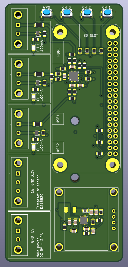
CAD drawing of flow control PCB

The PCB was designed with careful attention to signal integrity, power distribution, and thermal management. All components, including the relay drivers and temperature sensor interfaces, were organized to minimize wiring complexity while maintaining robustness. DIN rail mounting was incorporated into the layout for easy deployment in industrial environments. The design was verified through CAD-based placement optimization, electrical simulation of relay switching and power supply regulation, and prototype fabrication to validate real-world performance. All hardware design files, including schematics and PCB layouts, were delivered to the customer for documentation and future reference.

The control software was implemented in Python, running on the Raspberry Pi Zero. Key features included real-time temperature monitoring via thermal probe, threshold-based relay actuation for the primary valve, expandable logic to control two additional valves, manual override functionality via GPIO, and full MQTT integration for remote monitoring and control. We provided a ready-to-use Raspberry Pi image containing the complete codebase, Node-RED dashboard, MQTT configuration, and all dependencies, allowing the customer to deploy the system immediately with minimal technical setup.

To ensure reliable operation, the system underwent extensive integration testing, including functional verification of temperature-triggered valve actuation, validation of manual override functionality, testing of MQTT communication and Node-RED interface, power supply stress testing under operational loads, and verification of DIN rail-mounted PCB for electrical and thermal stability. This rigorous testing ensured that the unit operates reliably under real-world conditions while meeting safety and usability requirements.

We delivered a fully assembled, turnkey solution, including the Raspberry Pi Zero with preloaded software, DIN rail-mounted PCB with all components installed, electrically controlled relay and power supply, Node-RED dashboard and MQTT setup, as well as full source code, documentation, and installation instructions. The customer received a complete plug-and-play system, fully configured and ready for immediate deployment. In addition, training and technical support were provided to ensure seamless integration into their operations.
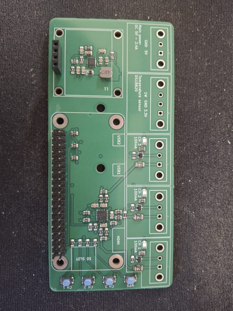
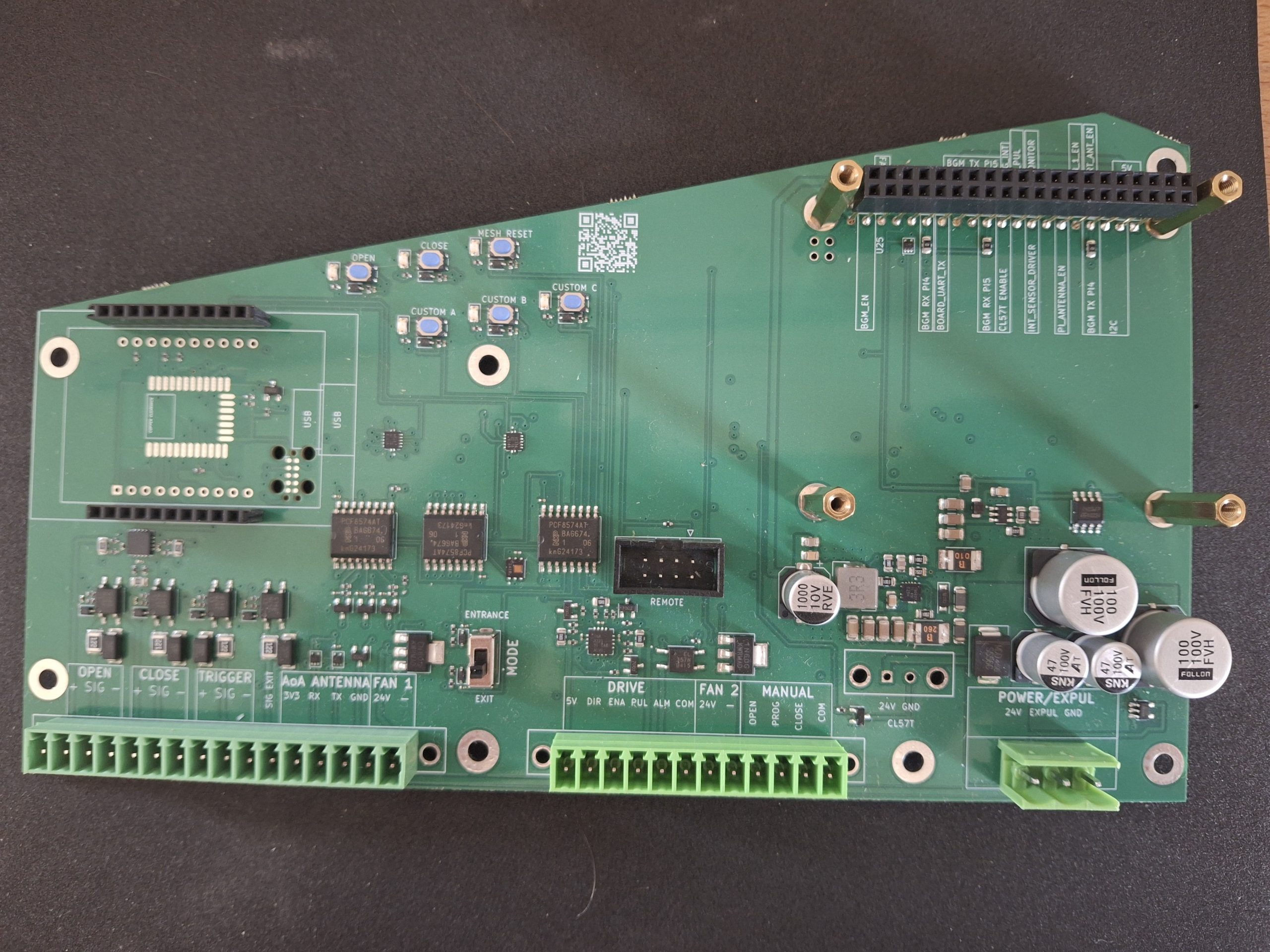
Manufactured PCB w/o display or RPi Zero.

The Flow Control Unit now enables automated, temperature-dependent valve control with full monitoring, manual overrides, and system expandability. By providing a fully integrated hardware and software solution, we reduced deployment time, simplified maintenance, and ensured robust operation in industrial conditions.
Smart Door Control

To help our client automate livestock movement, we developed a fully integrated smart door system combining custom electronics, real-time control, and high-level software. The solution reduced cabling by 50%, simplified installation, and added intelligent features like access logging, camera surveillance, and sensor health monitoring. Built around a robust microcontroller and Raspberry Pi combo, the system ensures reliable operation—even without network connectivity—and is managed centrally via an intuitive Node-RED interface and database-backed backend.

Smart mechanical systems are defined by the tight integration of mechanics, electronics, and high-level software. Our customer faced the challenge of controlling livestock by restricting access to certain areas based on the time of day. Their solution was a remote-controlled door with database integration. They provided a fully functional mechanical prototype, while we developed the electronics and high-level software integration.

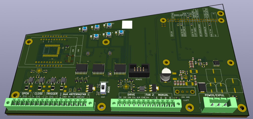
CAD design of PCB

Initially, we integrated all electronics onto a single PCB. External components—such as sensors and the motor controller—were connected via dedicated interfaces. We then developed firmware to handle time-critical door operations. Finally, we addressed full system integration, including camera surveillance and network connectivity. Time-sensitive tasks were managed by a microcontroller, while high-level functionality was delegated to a Raspberry Pi.

Safety and manual control were high priorities for our customer. Our design monitors system health by continuously measuring the current consumption of critical components. Additionally, manual override buttons were integrated into the design. While access schedules were managed via a central database, we enabled ad hoc changes through a Node-RED interface.

As our customer operated multiple doors on their property, we simplified management and maintenance by providing a central server for centralized access scheduling.

The initial challenge was to reduce setup complexity, which we addressed through a two-step approach. First, we designed dedicated interfaces for all sensors and the motor controller. These interfaces provided power and enabled reliable sensor readout. The motor controller was connected via its own hardware interface. This design reduced cabling by 50% and significantly simplified installation. To ensure proper EMI separation, all external signals were optically decoupled at their respective interfaces. Connections were implemented using Phoenix Contact terminal blocks, allowing easy plug-and-play integration for all external components.

While sensor and motor controller interfacing proved straightforward, power distribution required optimization. Together with the customer, we agreed on a single 24V power supply to power both the motor and all electronics. Our hardware design incorporated step-down converters to generate the required voltage domains. The power conversion circuitry was thoroughly tested using a dedicated prototype to validate stable operation under load and thermal stress.

The door control system was responsible for managing multiple real-time tasks. Beyond basic door motion control, it also had to detect and respond to animal passage with precise timing—ensuring that only one animal passed at a time, without startling livestock. All real-time logic was delegated to a Silicon Labs BG22EFR32 microcontroller. We selected the BGM220P module, which offers a robust design and integrated BLE functionality to support future wireless features.

Our design also included current monitoring for both sensors and the motor controller. This enabled detection of abnormal power consumption patterns, allowing us to predict potential sensor failures in advance. An early-warning notification system was integrated to prevent downtime and facilitate proactive maintenance. For manual overrides, we added local control buttons to the system.

At the system level, we chose a Raspberry Pi as the integration platform. This provided a cost-effective way to bridge low-level hardware control with high-level software capabilities, such as camera interfacing and network connectivity. The customer requested image capture of each animal passing through the gate. For this, we used a USB camera from ELF, which delivered fast and reliable snapshots.

Access scheduling was managed centrally via a Django-based application backed by a PostgreSQL database. The server was hosted on the customer’s premises and ran a stock Ubuntu distribution. It featured a RAID 1 dual-drive system to protect against data loss in the event of a hardware failure. To ensure continued operation during network outages, each door unit maintained a local database copy. At the customer’s request, we also developed a custom software mechanism to reconstruct the central access-time database from distributed logs stored at the individual doors.

Our door control unit removed two power supplies from the customer’s setup and reduced wiring by 50%. Furthermore, our design provided a tailored footprint, simplifying installation. This was achieved while meeting strict timing constraints and enabling smart features. External door sensors connect via optically decoupled inputs, ensuring system robustness in harsh EMI conditions. We tailored our motor interface to the customer’s preferred controller, enabling intuitive and easy installation. All external sensors are powered by our board, thereby allowing sensor health checks and reducing setup complexity. We integrated buck converters for generating all necessary power domains on-board.

Keeping maintenance in mind, we added on-board push buttons, thus enabling door control without a network connection or any smart features. Two switchable 24V, 200 mA fan outputs facilitate temperature control. Timing-critical operations are handled by a BG22EFR32 from Silicon Labs, while a Raspberry Pi manages smart features. This separation improves operational reliability by isolating physical controls from higher-level software layers. In the case of Raspberry Pi damage or network failure, the microcontroller ensures basic door operability.

Manufactured PCB as delivered to customer.

Integrated smart features include access control via a remote database, access logging, and camera surveillance. All features are customizable and controlled via an MQTT command set. A Node-RED user interface provides simple and intuitive handling.

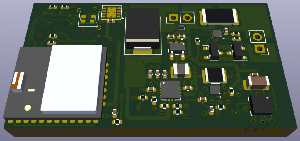
BLE tag enabling utilization tracking and localization for agricultural equipment

Utilization monitoring and localization of equipment are common challenges in agriculture. Our client wanted to reduce operational cost by acquiring actionable utilization data while supporting equipment location by staff. To address this we developed a custom BLE based asset tag. Our solution was based on a BGM220P facilitating certification and asset localization. Utilization tracking was realized by an on-board motion sensor tracking equipment vibrations. We delivered a fully functional tag and all associated design and firmware data. Commissioning was supported by our extensive documentation and onsite training ensuring familiarity and confidence with the new tags.

Our customer wanted to gain insight into the use of his agricultural assets to optimize maintenance costs. Additionally, he was facing the challenge of finding specific appliances scattered in his machine park. Two readily available solutions were evaluated and fell short in key areas. GPS modules provided suitable asset tracking capabilities but showed high power consumption limiting battery lifetime. In contrast, BLE beacons offered a sufficient battery lifetime and asset tracking options yet failing to provide actionable asset utilization data. The first challenge was to identify a suitable method for sensing asset utilization. Monitoring a motion sensor promised a straightforward implementation with standard components. Moreover, on-board motion sensing has proven reliable in harsh condition as faced by automotive or aviation applications. In addition, the requested battery lifetime put constraints on power usage and associated computation time. Critically, any device had to endure rough outdoor conditions while fitting stringent form factor requirements. This warranted a custom full stack solution, integrating the stringent space requirements and special asset utilization tracking.

We were presented with two major challenges. Creating an asset utilization monitor with minute-level precision. Additionally, we were facing the challenge of asset localization when not in use.

The customer’s assets were heavy agricultural equipment used in agricultural operations. All assets exhibited significant vibrations when in use. These vibrations could easily be detected at the intended tag mounting point. Utilizing a motion sensor in our design enabled robust utilization detection. Selecting a sensor with a wake-up on motion feature facilitated our further design.

As for the localization challenge we decided to rely on BLE RSSI tracking. After comparing different platforms we settled for a BGM220P moduly by Silicon Labs. This module offers sufficient interfaces for peripheral electronics. Moreover it is FCC and EMI certified, which sped up development significantly. Connecting the motion sensor wake-up interrupt to the BGM220P allowed to keep active electronics in a low power state while the asset is in use. This allowed power saving schemes further extending battery life.

After solving utilization detection we implemented a BLE advertisement scheme to enable asset localization when not in use. An array of freely available BLE sniffer smartphone apps could then be used for asset localization. Utilization time data could be extracted by connecting with a dedicated anchor consisting of a standard Raspberry Pi 4. Once the asset is not in use we commence BLE advertising. The Raspberry Pi is scanning for valid BLE identifiers. If a valid identifier is discovered the Raspberry Pi connects to the tag and extracts all new asset utilization data.

We built our system on a simple prototype board. This prototype provided a twofold advantage. We were able to supply the customer with hardware for a successful proof of concept. Doing so further increased the customer’s confidence in our solution. Additionally, the prototype board allowed hardware in the loop testing of our final system.

While the proof of concept was ongoing, we started developing all necessary periphery electronics. Selecting LiPo management components from Texas Instruments ensured easy compatibility and enabled a fast design cycle. Once all components were selected, we tackled the PCB design. Here we faced the tight spatial requirements imposed by our customer. Form factor compatibility was verified by CAD models.

Firmware development proceeded in parallel to our hardware development. Commencing from a simple BLE stack we first integrated drivers for all peripheral components. Initially focusing on asset utilization tracking and later advancing to asset localization and data retrieval. The final step of firmware development focused on battery management, minimizing power consumption and allowing robust user interaction.

We delivered the final product to the customer and supported initial commissioning. Our system integration was supported by on-site training for all employees. All hardware design files and firmware source code was provided as well, supplemented by extensive documentation.

We developed a custom form-factor BLE tag tailored to our customer’s asset tracking needs. At the tag’s core is a BGM220P BLE module by Silicon Labs. This module provides necessary FCC and EMI certification, and a robust platform for our custom BLE integration. Moreover the BGM220P offers rich peripheral interfaces enabling easy integration with additional electronics. A single cell LiPo battery powers the tag. As per the customer’s request, we designed a full charging circuit. This integrates battery protection, charging and monitoring. A two-pole magnetic connector allows easy charging with any sufficiently powered 5V supply. BLE is the backbone of our asset tracking solution. It is fully managed by our custom firmware. The customer’s special demand for asset utilization tracking was realized by an on-board motion sensor. Furthermore, we implemented a battery status report via BLE. When charging the tag uses an LED indicator to signal when the battery is full. We doubled the battery lifetime by utilizing the tag’s motion sensor for power-saving algorithms. All hardware development files and firmware source code was delivered to the customer. This was supplemented by extensive documentation and on-site training for all employees.